Using Wideband Diplexing Configuration for Earth Station Uplink Systems
With the increasing demand on broadcast RF systems, there is an endless search for higher power capacity, more flexibility and better reliability of RF output to ensure an earth station is capable of transmitting multi-carriers to satellites. There is also demand for the RF system to provide more uplink power, work to a higher efficiency, support fast reconfiguration as well as remain environmentally green in efforts to reduce carbon emissions.
AsiaSat Tai Po earth station has a new uplink system which applies the concept of output multiplexers (OMUXs) onboard satellite to the ground earth station. Below is a comparison of the new design against the traditional system, summarising the advantages of the new uplink system and demonstrating the reliability of the current uplink system.
Power combining techniques
A low loss, high efficiency uplink system is very desirable in an earth station. There are a few techniques that can be used to attain more power from a high power amplifier (HPA). For example, outdoor HPAs are installed in the vicinity or inside the hub of the antenna feed as shown in Fig. 1 to reduce the path loss. However, only HPAs with small dimensions can be mounted outdoors because of the limited hub space. It is difficult for outdoor units (ODUs) to be applied to a large-scale and flexible RF uplink system. In addition, MTTR (mean time to repair) is longer due to location of the outdoor HPAs. More seriously, first time troubleshooting and recovery cannot be performed during adverse weather periods.
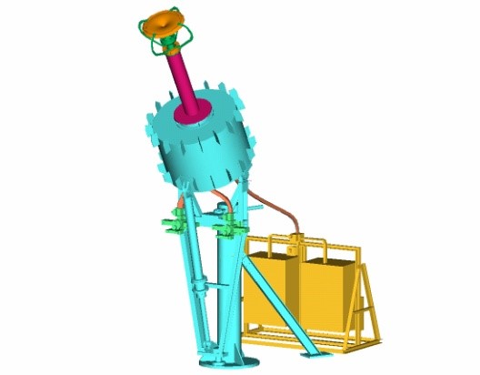
Fig. 1 Outdoor HPAs in vicinity of the antenna feed
There currently are several other power combining techniques that can be implemented to increase the output power and each has its own unique features specified below.
Phase combining
Phase combining is a popular means to efficiently increase the power in a RF system. It can be achieved using a Magic-T device and a phase shifter as illustrated in Fig. 2. The combined two signals from two HPAs must be in the same frequency. Ideally, the two input signals can be adjusted in phase and the output port sums full power from both HPAs. In reality, some out-of-phase power will be generated and absorbed by the dummy load in the isolation port. Phase combining scheme for broadband HPAs such as travelling wave tube amplifiers (TWTAs) is usually optimised at the mid-band frequency. Therefore, the band edge frequencies will suffer performance degradation. Moreover, the phase will change with temperature and aging. Adjusting the phase shifter to periodically optimise the phase is required but will increase risk to uplink service stability. In addition, fast redundancy implementation and swap out of TWTAs requires phase adjustment and causes longer interruption to the uplink service.
Fig.2 Phase combining
Narrow band diplexer combining
Diplexer combining is achieved using a diplexer to combine two input channels into a single output with low insertion loss. It is normally a narrow band device and suitable for combing Klystron power amplifiers (KPAs). Wide guard band is required (e.g. ±40MHz) due to diplexer rejection requirement. As shown in Fig. 3 a number of diplexers cascading the odd number and even number of transponder channels respectively can be combined by a 3dB hybrid at the end into one single output. As a result, the power efficiency of all the connected KPAs are less than 50% due to the 3dB hybrid loss. Since the channel frequency is fixed, it is difficult, if not impossible, to modify this RF system without service interruption when the uplink frequency changes, offering very low flexibility and power efficiency.
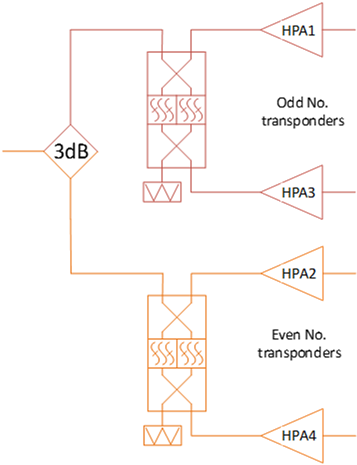
Fig.3 Narrow band diplexer combining
Traditional uplink systems in Tai Po earth station
Traditional uplink systems in Tai Po earth station used narrow band diplexer combining technique. Fig. 4 shows a diagram of the typical diplexing configuration used in Tai Po earth station uplink systems. The structure of the diplexer is illustrated in Fig. 5. Each diplexer has two input channels and there must be a frequency separation (i.e. guard band) between the two channels due to the restriction of roll-off of the two channel filters in the diplexer. Thus, Channel 1 and Channel 3 are two input channels to the first diplexer which is cascaded with the second diplexer with Channel 5 as its other input. Channel 2, 4 and 6 are blocked as guard bands in this branch. Diplexers cascade all the odd number of channels and even number of channels in this way respectively. Finally the last two diplexers are combined by a 3dB hybrid. The limitations of this diplexing configuration are:
- Channel bandwidth is as narrow as 36MHz for C-band or 54MHz/33MHz for Ku-band, namely a transponder bandwidth in this case;
- Channel separation as at least ±40MHz for 36MHz transponders in the C-band is required between any two of odd number channels or any two of even number channels;
- The more number of diplexers the larger path loss will be introduced;
- Due to wide channel separation, diplexers are usually connected to KPAs whose number is as many as the number of channels in the uplink system;
- 3 dB hybrid will cause power loss of each channel by 50%;
- The transmit channel assigned to the system is restricted;
- Flexibility achieved for variational uplink frequencies is low.
- Configuration change will require system to go off line.
- Use of HPA power is limited to the bandwidth of diplexer
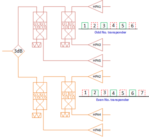
Fig. 4 The diagram of the typical diplexing configuration used in Tai Po earth station uplink systems
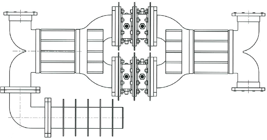
Fig. 5 The structure of the typical narrow band diplexer
New design of wideband diplexing uplink systems
To increase the power capability and flexibility, AsiaSat engineers designed a novel uplink system in Tai Po earth station where selected C-band uplink systems have been modified by replacing the traditional narrow band diplexers with wideband diplexers which use the similar concept of OMUXs currently implemented onboard satellites. A diagram of the newly designed wideband diplexing configuration used in Tai Po earth station uplink systems is shown in Fig. 6. The bandwidth of each channel filter in this case is more than 300MHz which can transmit around seven channels (i.e. C-band transponders) with a 4MHz guard band between any adjacent two channels. For a typical AsiaSat satellite, there are fourteen transponders in total for C-band in one polarisation. Therefore only one wideband diplexer is needed for combining two broadband HPAs for C-band uplink in one polarisation to achieve an increase in output power.
Similarly, there is also a requirement for a frequency separation between the two channel filters. One of the channels will be blocked in using the configuration as illustrated in Fig. 6. To overcome this, a waveguide switch is added to bypass the diplexer when the required uplink power can be handled by a single HPA. The guard-band is not required in this situation. Alternatively, the waveguide switch will route the output of one HPA to pass through the diplexer and combine with another HPA to increase the power capacity when the required uplink power exceeds the capacity of the single HPA. The newly designed configuration simplifies the uplink system, and the insertion loss of the diplexers is significantly reduced from over 3dB to about 0.3dB. In addition the system provides configuration flexibility and easy upgrade when traffic change is constantly required. This design can be cascaded as well due to its low loss characteristic but certainly more channels will be blocked as more guard bands are required.
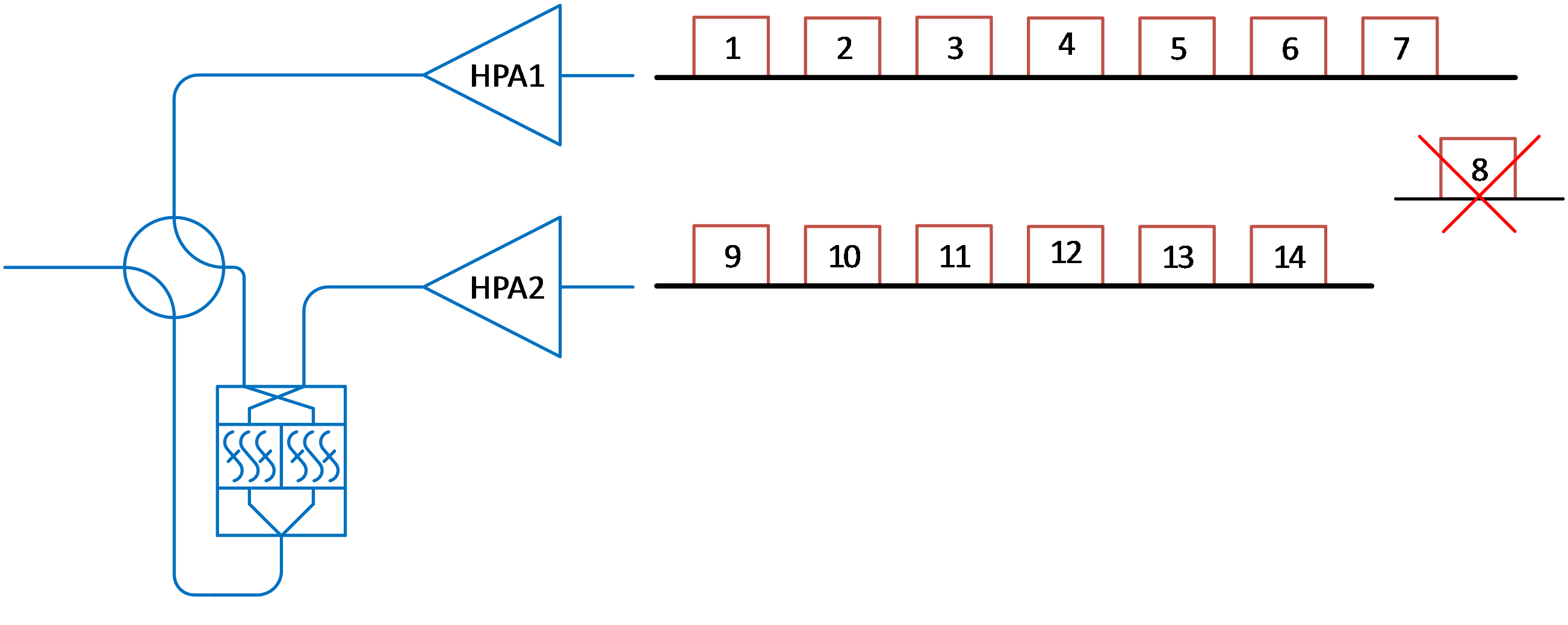
Fig. 6 The diagram of the newly designed wideband diplexing configuration used in Tai Po earth station uplink systems
The wideband diplexer was designed and manufactured by a vendor according to AsiaSat requirements. The unit is qualified for high power handling and passive intermodulation (PIM) requirements. The pictures of the wideband diplexer is shown in Fig. 7. In comparison, the traditional and newly designed diplexers are displayed together in Fig. 8 with measured dimensions of 565×317×115mm vs. 350×220×95mm. It can be seen that the newly designed wideband diplexer is light and compact in size.

Fig. 7 Pictures of the newly designed wideband diplexers
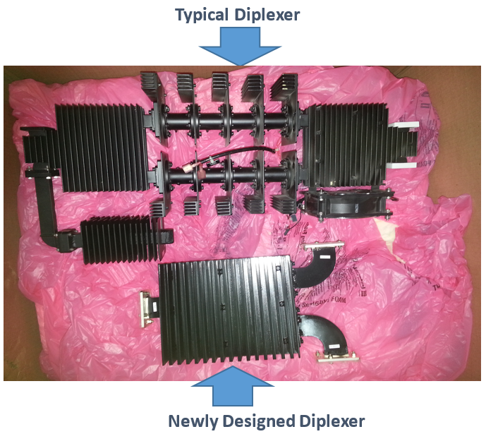
Fig. 8 Pictures of the traditional diplexer and the newly designed wideband diplexer
Uplink systems employing newly designed wideband diplexing configuration in the RF room of Tai Po earth station are demonstrated in Fig. 9. The embedded wideband diplexers occupy a compact space on the rack.
Fig. 9 Uplink systems employing newly designed wideband diplexing configuration in the RF room of Tai Po earth station
RF performance of the newly designed wideband diplexers has been measured as shown in Fig. 10. It indicates that the return loss of the both channels is better than 20dB and the maximum insertion loss in the passband is less than 0.2dB. Out-of-band rejection is better than 26dB. Each port of the diplexer can provide 2000W power handling capability and the aggregate power of as high as 4000W can be obtained at the output port.
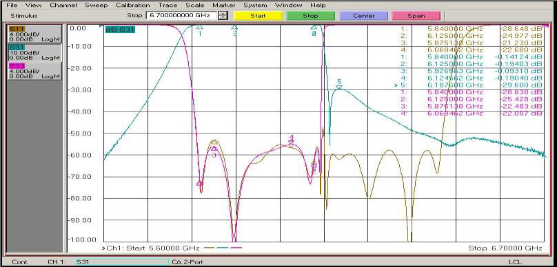
(a) Input from HPA 1: Channel 1 to 7 as shown in Fig. 6
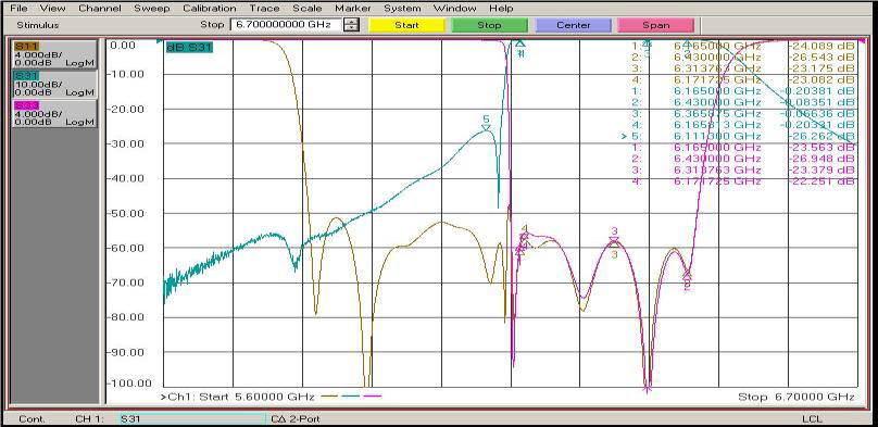
(b) Input from HPA 2: Channel 9 to 14 as shown in Fig. 6
Fig. 10 Frequency response of the uplink systems employing newly designed wideband diplexers in the RF room of Tai Po earth station
Conclusion
The design technique of OMUXs on satellites has been adopted to design the unique wideband diplexing configuration for the uplink systems used in AsiaSat Tai Po earth station.
The newly designed diplexing configuration make the uplink system simplified and compact in size. The system provides flexibility for reconfiguration and is easy for upgrade when traffic change is frequently required. More importantly, better RF performance is achieved by significantly reducing the insertion loss, eliminating channel frequency limitations and increasing power capability. It allows AsiaSat to provide our customers with high efficiency in power usage and also provide a solution promptly to our customers’ ad-hoc uplink request such as frequency/bandwidth change or single carrier to multi-carrier application. Thus our customers can enjoy high-quality service and good user experience.
About the Authors
Tommy Fu is AsiaSat’s Senior Communications Systems Engineer. He received Bachelor of Computer Science from Victoria University of Technology. Mr. Fu has 15 years of experience in SatCom industry. He is responsible for TT&C tracking antenna, Teleport communication antenna, RF systems and other Earth Station projects implementation.
Rui Zhang is AsiaSat’s Senior Communications Systems Engineer. She received the Bachelor and Master degrees from Nanjing University of Science and Technology, Nanjing, China, and the Ph.D. degree from the University of Waterloo, Waterloo, ON, Canada, all in Electrical Engineering. Dr. Zhang has been with AsiaSat for 7 years specializing in spectrum planning and management. She is responsible for frequency coordination, spectrum regulatory issues and protection of spectrum for satellite communications.
